Ambitape
Ambient monitor backlight using BlinkyTape

AmbiTape is companion software for the BlinkyTape. It allows you to add real-time ambient backlighting effects to your computer monitor. This effect can make it seem like the image on your monitor extends outside of the frame on the screen. We think it looks pretty cool!
AmbiTape is based on Adafruit’s Adalight software, which uses Processing to capture colors from different regions of your screen and send them out to the LEDs via USB. Adalight, in turn, is inspired by the Ambilight feature of Philips’ LCD HDTVs.
This entire project can be done in as little as 30 minutes!
This tutorial will guide you through:
- Downloading the AmbiTape software
- Mounting the BlinkyTape to your display
- Configuring AmbiTape for your display
Software Installation
Install Processing
The Processing development environment runs in Windows, Mac OS X, and Linux.
BlinkyTape is known to work with Processing version 3.3.
You can find downloads and detailed install instructions for your platform on the Processing Getting Started page.
Install the BlinkyTape Processing Libraries
Now that you have downloaded Processing, it’s time to download some helper code and examples. This stuff lets us make our programs a bit more simply than if we had to do everything from scratch, as you’ll see later on.
Get it
Here is the link to what we want. This is a live GitHub repository, so it should always be up to date. Use the “Download ZIP” link on the right of the page.
Install it
Unzip this folder in your Processing libraries folder – this is located at Documents/Processing/libraries on Mac or My DocumentsProcessinglibraries on Windows.
Important: When you unzip the file, the resulting folder will probably be called something like BlinkyTape_Processing-master — delete everything after the underscore, or Processing won’t import the library. (It doesn’t like special characters.)
Install the ControlP5 library
The last step before firing up the AmbiTape example is to install a Processing library called “ControlP5.” This helps us draw interface elements. To install it, first start Processing, then open the Sketch menu, followed by Import Library, then Add Library. A new Library Manager window will appear. In the “Filter your search…” box, type in ‘controlp5’ and click the ControlP5 item that appears to install it.
Restart Processing, if it is running.
You should now see the BlinkyTape examples if you go to File -> Examples. This will open a chooser-type window so you can scroll through all of your installed examples for Processing. You’ll find ours in Contributed Libraries -> BlinkyTape.
Starting AmbiTape
- Connect your BlinkyTape to your computer via USB
- Open the AmbiTape sketch in Processing:
Find it at BlinkyTape/examples/AmbiTape/AmbiTape.pde - Click the Run button.
Your BlinkyTape should light up, projecting colors from your display!
Mounting The BlinkyTape
The “Drape” Method (Estimated Time: 5 minutes)
Benefits: Easy to install. Easy to remove.
Drawbacks: Projects light out to the sides rather than back against the wall, reducing the effect.
This method is simplest, though the results are not as pretty as with the other methods described below.
Simply drape the BlinkyTape over the top of your display. You can crease the edges slightly to help everything stay down. Clear tape or double-sided tape should be enough to keep it in place. You may want to remove the BlinkyTape from its silicone tubing if the sides don’t want to stay down.
The “Twist” Method (Preferred. Estimated Time: 10 minutes)
Benefits: Easy to install. Easy to remove. Projects light against the wall.
Drawbacks: Requires creasing the BlinkyTape. Results in a “dead” pixel at each turn due to pixels pointing in toward the monitor.
The backlighting effect works much better when the LEDs are projecting directly against a wall. With a little BlinkyTape folding (Blinkigami), we can get the BlinkyTape into a rectangular shape that lies flat.
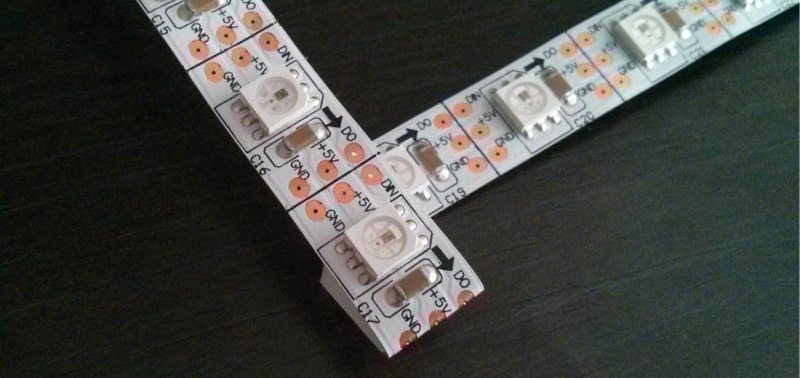
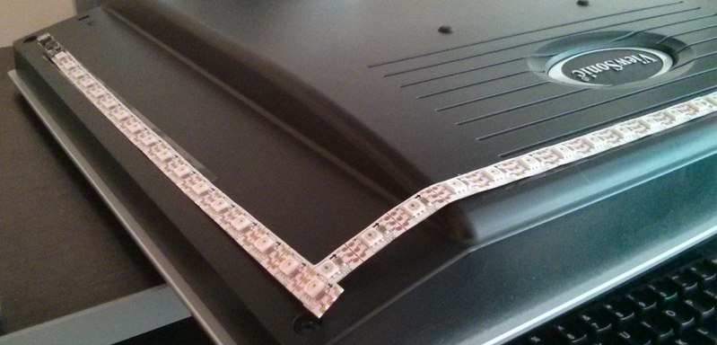
Here is an image of the BlinkyTape, folded over so it makes a 90° turn, with all visible LEDs facing the same direction. The silicone tubing has been removed to make it easier to fold and mount the BlinkyTape.
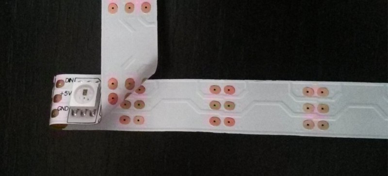
This image shows the fold from the back, which might give a better idea of how the fold is done. This image shows the “sacrificial” LED, which will be facing in towards the monitor. We’ll configure the AmbiTape software to ignore this LED later.
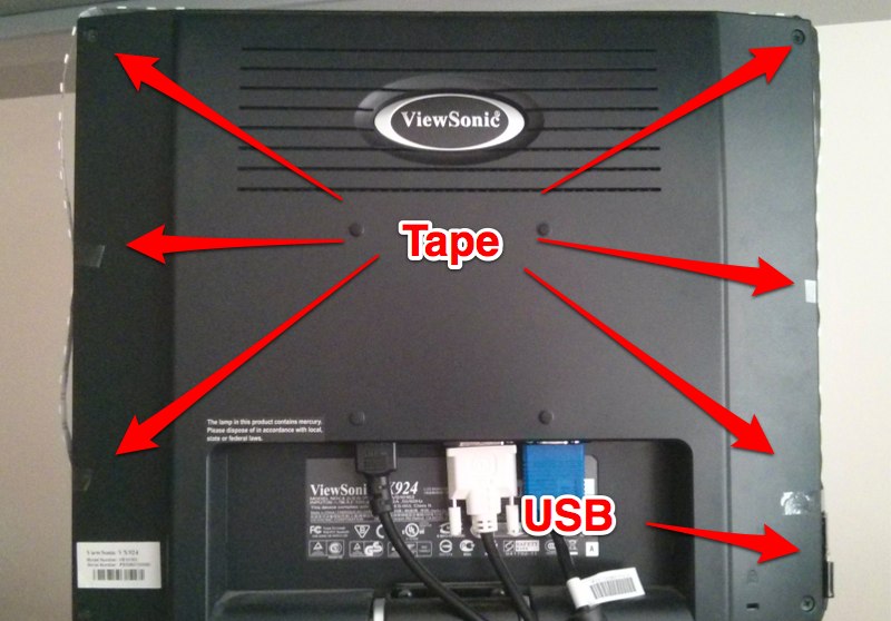
Here is an image of the complete installation. The folded BlinkyTape is attached to the back of the monitor using double-sided sticky tape.
The “Hardcore” Method (Estimated Time: Hours)
Unless you have a very small monitor, the BlinkyTape is probably not long enough to completely cover each edge along the back of your monitor.
However, it is totally possible to spread out the BlinkyTape’s 60 RGB LED pixels to cover your monitor, no matter how large it is!
Benefits: Projects light against the wall. Fully covers the perimeter of your screen.
Drawbacks: Requires cutting and reassembling the BlinkyTape. This is not easy to undo once it is done!
Because we favor quick hacks and reusability, we haven’t carried out this method ourselves, but we have some hints for those that want to try it out.
What You’ll Need
- BlinkyTape
- Wire cutters or other tool capable of cutting the BlinkyTape’s flexible backing.
- 3 colors of stranded wire (14ga should be fine).
- A soldering iron and solder.
The Process
- Remove the BlinkyTape from its silicone tube.
- Cut the BlinkyTape into the appropriate number of segments for your setup.
- Try to cut exactly between the solder pads in between pixels. See the photo above for help.
- Make sure you don’t cut the BlinkyBoard off the end!
- Cut your stranded wires into the appropriate lengths to create “jumpers” between each segment of BlinkyTape.
- Solder your tape back together with the jumper wires in between.
- Make sure to begin with the segment that has the BlinkyBoard attached!
- The order of the power, ground, and signal pins matters, so make sure all of the text is facing the same way!
Determining Appropriate Segment Sizes and Wire Lengths
The correct size and number of segments is going to vary widely based on your screen size, how you want to mount the LEDs, and your personal preferences.
Start by determining the number of “clusters” you want to place. If you’re not afraid to spend a good deal of time soldering, you can cut your BlinkyTape into many small segments (e.g. 20 segments of 3 pixels each, 12 segments of 5 pixels each, etc.). This step determines how many sets of jumpers you will have to cut and solder. For example, 20 segments requires 19 sets of jumper wires.
Next, measure out the perimeter along the back of your screen that you intend to cover. This can be as simple as measuring the width and height of your monitor where you intend to mount the LEDs, adding up both numbers, and multiplying by two.
Finally, determine how long each set of jumper wires should be. This can be a pretty simple equation like:
jumper_length = (perimeter – 100cm) / number_of_jumpers
You will probably want slightly different lengths for any sets of jumpers that have to turn a corner, in order to help the wires lay flat.
Configuring AmbiTape for your Display (Estimated Time: 20 minutes)
Each AmbiTape installation is different and depends on the size of your monitor and your mounting method. To get the best lighting effects with AmbiTape, you’ll need to tell AmbiLight how to map each pixel to a particular region on your display.
For the time being, with our apologies, this is a manual process and requires a bit of thought. You will need to edit AmbiTape.pde to match your setup.
Update the displays array
AmbiTape breaks your screen down into a small number of regions. You can think of this as a tiny “virtual screen”, where each block along an edge corresponds to an LED.
Below is an example display array for a 19″ monitor with a 4:3 aspect ratio:
static final int displays[][] = new int[][] {
    {0,26,20} // Screen 0, 26 LEDs across, 20 LEDs down
};
You may notice that the BlinkyTape’s 60 LEDs does not come close to covering the 2 * (26 + 20) = 92 pixels described here. In this setup, the BlinkyTape covers the top edge of the screen and most of the left and right sides. The particulars of this are handled below.
Update the leds array
To determine which pixel corresponds to which region on the screen, the leds array lists a screen coordinate for each pixel in the BlinkyTape, starting with the LED that is attached to the BlinkyBoard.
Here is an example leds array for the 19″ monitor described above. Note the two “dead” pixels that are assigned to screen -1. This indicates to AmbiTape that it should leave those pixels black rather than lighting them up.
static final int leds[][] = new int[][] {

// Left Side
{0,0,17}, {0,0,16}, {0,0,15}, {0,0,14}, {0,0,13}, {0,0,12},
{0,0,11}, {0,0,10}, {0,0, 9}, {0,0, 8}, {0,0, 7}, {0,0, 6},
{0,0, 5}, {0,0, 4}, {0,0, 3}, {0,0, 2}, {0,0, 1},

// Top Side – “dead” pixels indicated with a -1
{-1,0, 1}, {0, 1,1}, {0, 2,1}, {0, 3,1}, {0, 4,1}, {0, 5,1},
{0, 6,1}, {0, 7,1}, {0, 8,1}, {0, 9,1}, {0,10,1}, {0,11,1},
{0,12,1}, {0,13,1}, {0,14,1}, {0,15,1}, {0,16,1}, {0,17,1},
{0,18,1}, {0,19,1}, {0,20,1}, {0,21,1}, {0,22,1}, {0,23,1},
{0,24,1}, {-1,25,1},

// Right Side
{0,25, 1}, {0,25, 2}, {0,25, 3}, {0,25, 4}, {0,25, 5}, {0,25, 6},
{0,25, 7}, {0,25, 8}, {0,25, 9}, {0,25,10}, {0,25,11}, {0,25,12},
{0,25,13}, {0,25,14}, {0,25,15}, {0,25,16}, {0,25,17}
};
Further Notes on Configuration
Every display and application can be a bit different, so expect to play with the configuration as you go. Some things to watch out for:
Black Bars
Many movie players end up adding black bars to the top/bottom or left/right sides of a display when the video’s aspect ratio doesn’t match up with the display’s.
One way to work around this is to update your configuration to pull colors from closer to the center of the display.
OS X Menu Bar
The OS X menu bar is shown almost all the time, and is almost uniformly bright white. This makes for a pretty uninteresting backlight display! A simple fix is, as with the black bars, to adjust your configuration to pull colors from a bit lower than the top row of pixels. In the leds example, above, the top row of LEDs get their color from the Y = 1 row, rather than the Y = 0 row.