BlinkyPendant Startup Issue
20 June 2024
This post

Seaching for the issue
First guess: Power regulator not turning on reliably
The first guess was that the power regulator itself was unable to start correctly. This could be for example because the output load cap was too high, causing an input current spike that drops the battery voltage too low, and puts the part into a bad state.
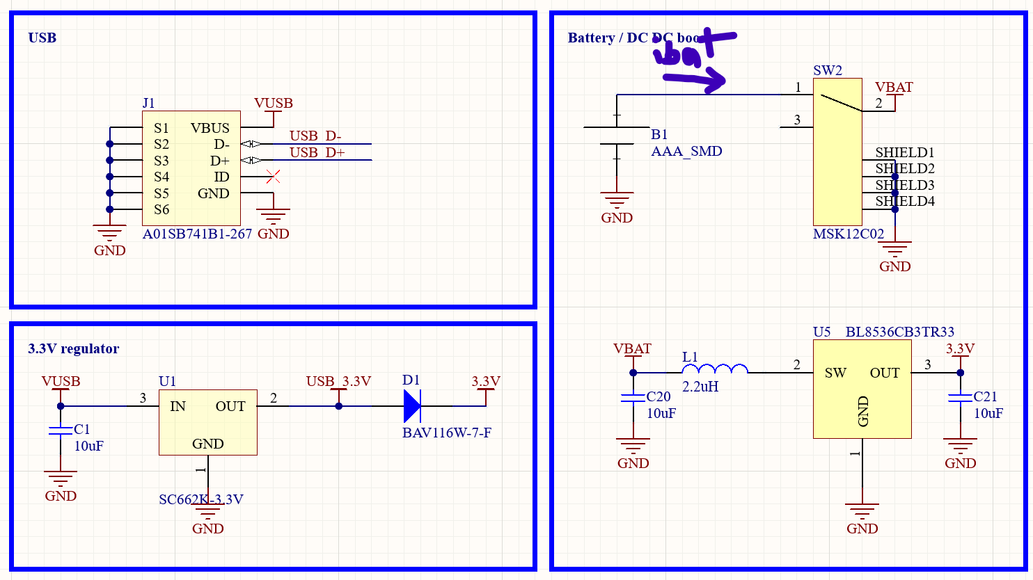
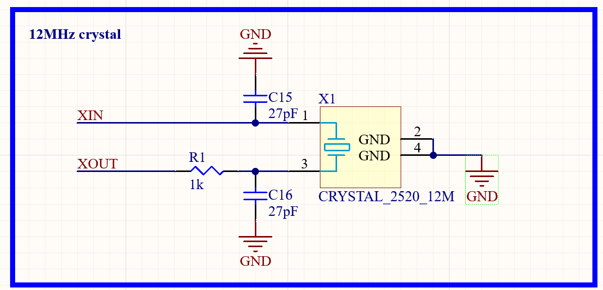
The schematic for the power circuitry looked like this:
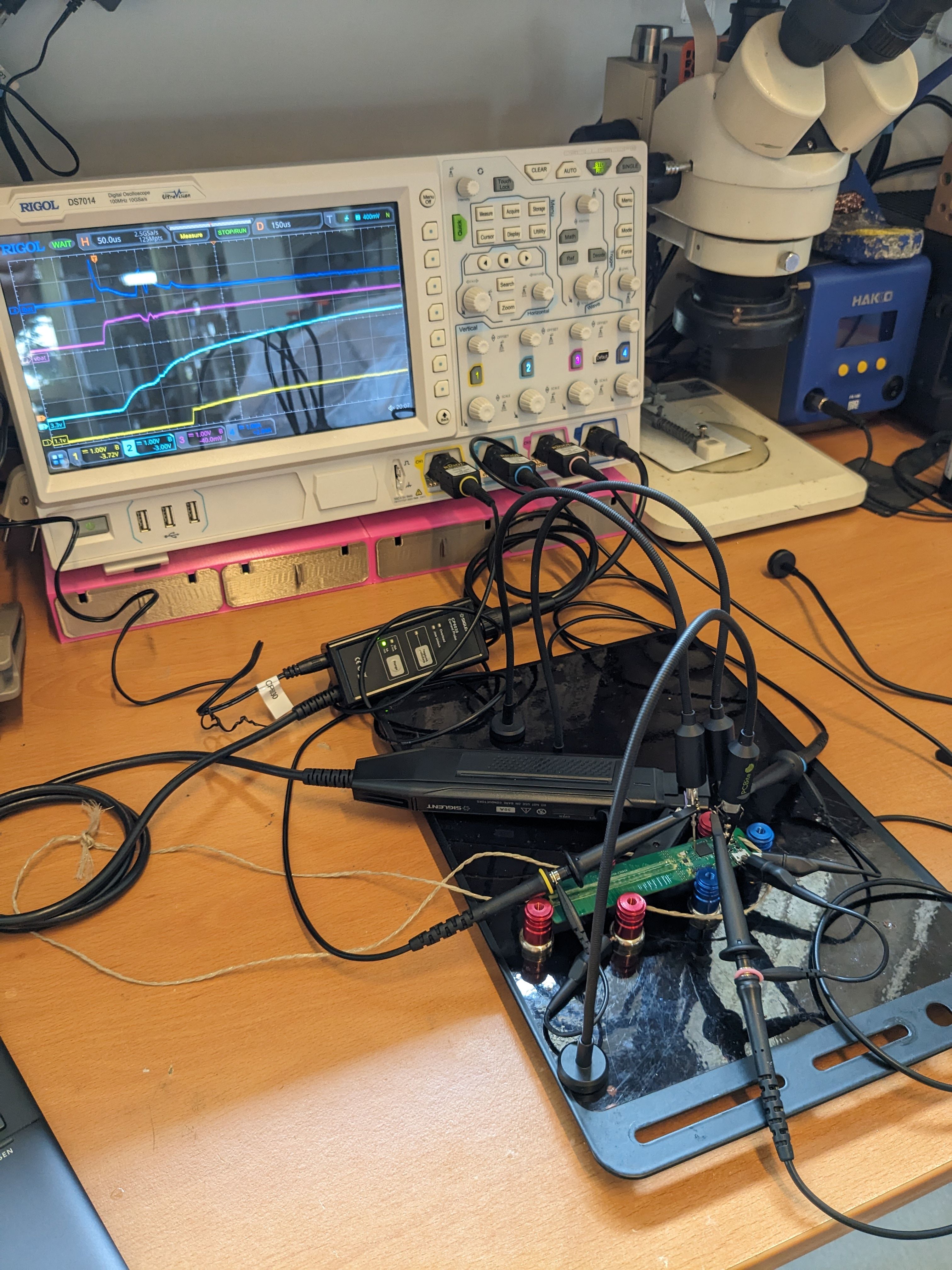
To test this idea, the power-on current and voltage waveforms were captured using a scope. The scope was set to trigger on the 3.3V line going above a small threshold.
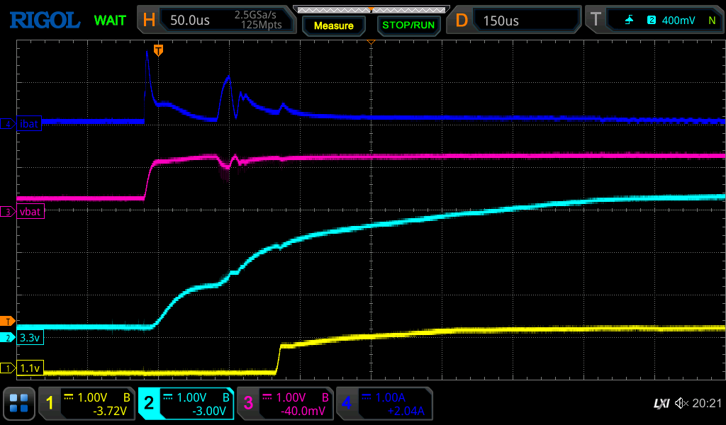
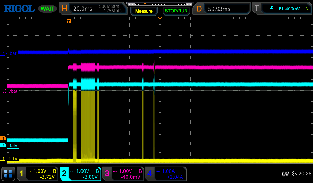
A typical waveform for a failed startup was:
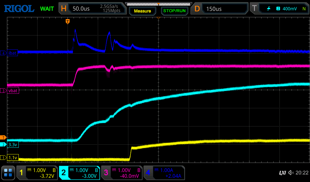
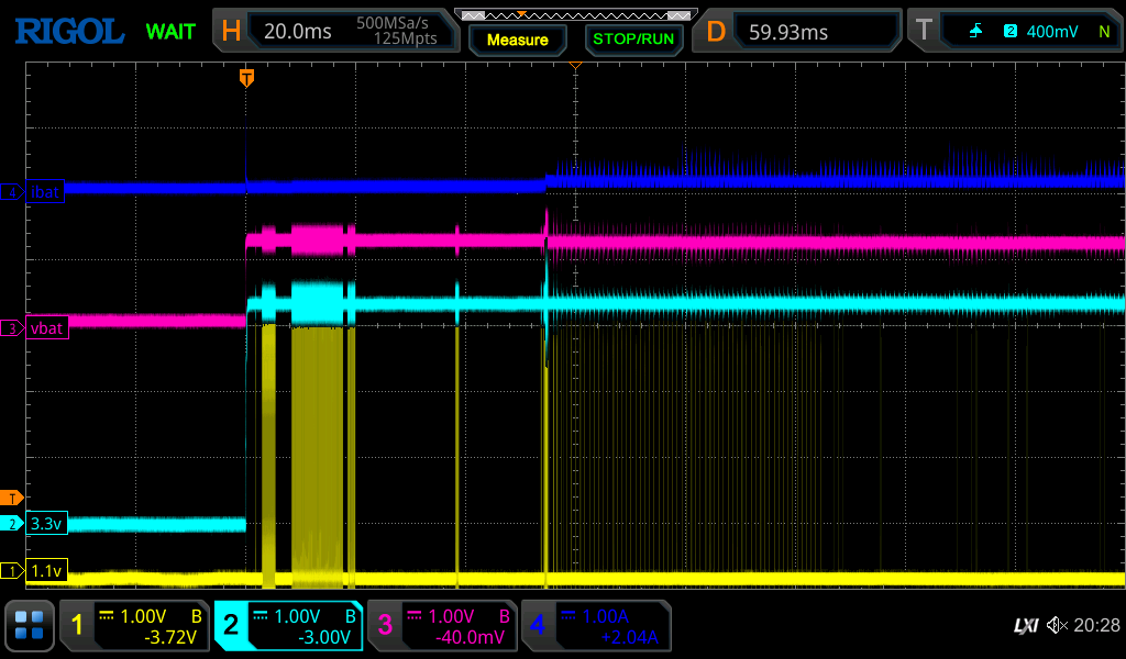
And for a successful startup:
These looked almost the same, and were very repeatable. In particular, the 3.3V line reached a steady state in both cases, and the 1.1V rail (generated by the RP2040) also turned on cleanly, and at a similar position in the startup.
Second guess: Brown out causing boot instability
The next guess is that the RPI2040 was attempting to turn on too quickly, and somehow browning out. One possibility was that it wasn’t the RP2040, but actually the SPI flash that could be browning out. The RP2040 boots from the flash device, so if there was an issue here it cause the start-up problem.
An RC network with a random large time constant was soldered onto the ‘run’ input pin, in order to delay startup. Unfortunately, this didn’t have a noticeable effect on the system behavior.
To monitor the flash behavior, the SCK line of the SPI flash was probed (labeled ‘1.1V’ on the scope captures below)
A failure waveform looks like this:
and a successful one like this:
There was a clear difference in the two captures. Both start with a similar signature, with a few bursts of SPI access. The failure has a longer delay after the first bursts, and the second showed a bunch of SPI access after a small delay.
Because it didn’t appear to have an effect on startup, the RC circuit was removed from the test board. Searching through the RPi 2040 literature, it isn’t recommended anywhere, anyway.
Third guess: Firmware issue
The third guess is that this was caused by a firmware issue. Perhaps a value was set correctly in a previous version of the SDK, but needs to be done manually in the current version? To test this theory, a pre-built binary from a different project that was known to run correctly on a RPi Pico was loaded onto the BlinkyPendant board.
The alternate binary showed the same power-on issue, so an SDK change was likely not the issue. To double-check, the BlinkyPendant firmware was also loaded onto the RPi Pico; it seemed to work on that platform, so this didn’t seem like a regression in the SDK was to blame
Fourth guess: Crystal problem
The next step was to search the internet for RP2040 startup issues. One that showed up on some bug trackers was that the default setting for PICO_XOSC_STARTUP_DELAY_MULTIPLIER caused issues with third party boards. This setting changes the amount of time that the RP2040 waits for the 12MHz xtal to start, before switching to it as a clock source.
Changing this setting to something random and large (64) allowed the firmware to boot correctly, repeatedly, so this seemed to be the issue.
Fixes
Software fix: Change PICO_XOSC_STARTUP_DELAY_MULTIPLIER
The quick fix was to change the PICO_XOSC_STARTUP_DELAY_MULTIPLIER from it’s default of 2, to something much larger. This can be done in the project CMakeLists.txt file:
target_compile_definitions(main PUBLIC
    PICO_XOSC_STARTUP_DELAY_MULTIPLIER=64
)
However, the RPi Pico reference board does work with the default value. This suggests that the BlinkyPendant circuit design was marginal.
Hardware fix: Choose better load caps
When designing the prototype, the default values of the load capacitors (27pF) from the example RP2040 circuit were used as placeholders. Unfortunately their values were not reconsidered before production of the prototypes.
A quick calculation of their optimal value with the actual crystal used (using a guess for the stray capacitance) put them at:
CL = 12pF (from xtal datasheet)
Cstray = 4pF (guess)
CX = CX1 = CX2 (use the same value for each load cap)
The the value of the load capacators can be calculated by:
CL = ((CX1 x CX2) / (CX1 + CX2)) + Cstray
CL = CX/2 + Cstray
CX = (CL - Cstray)*2
CX = (12-4)*2 = 16pF
To verify this, a range of different load capacitor values were placed onto the BlinkyPendant2 prototype, and the resulting xtal frequency was measured using a spectrum analyzer:
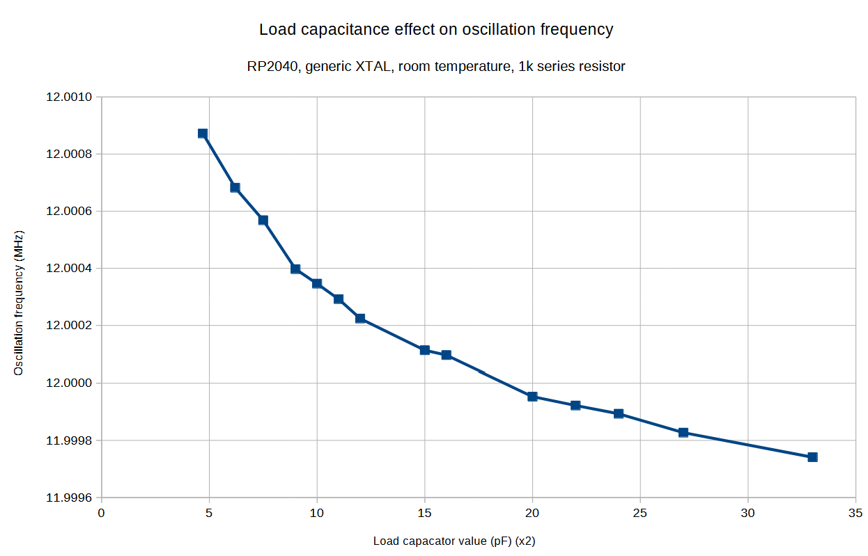
It appears that 18pF is the closest value. Working backwards, this puts the board stray capacitance closer to 3pF.
Verifying the fix
With both of these fixes in place, the final step was to verify that they would work over a larger sample of power cycles.
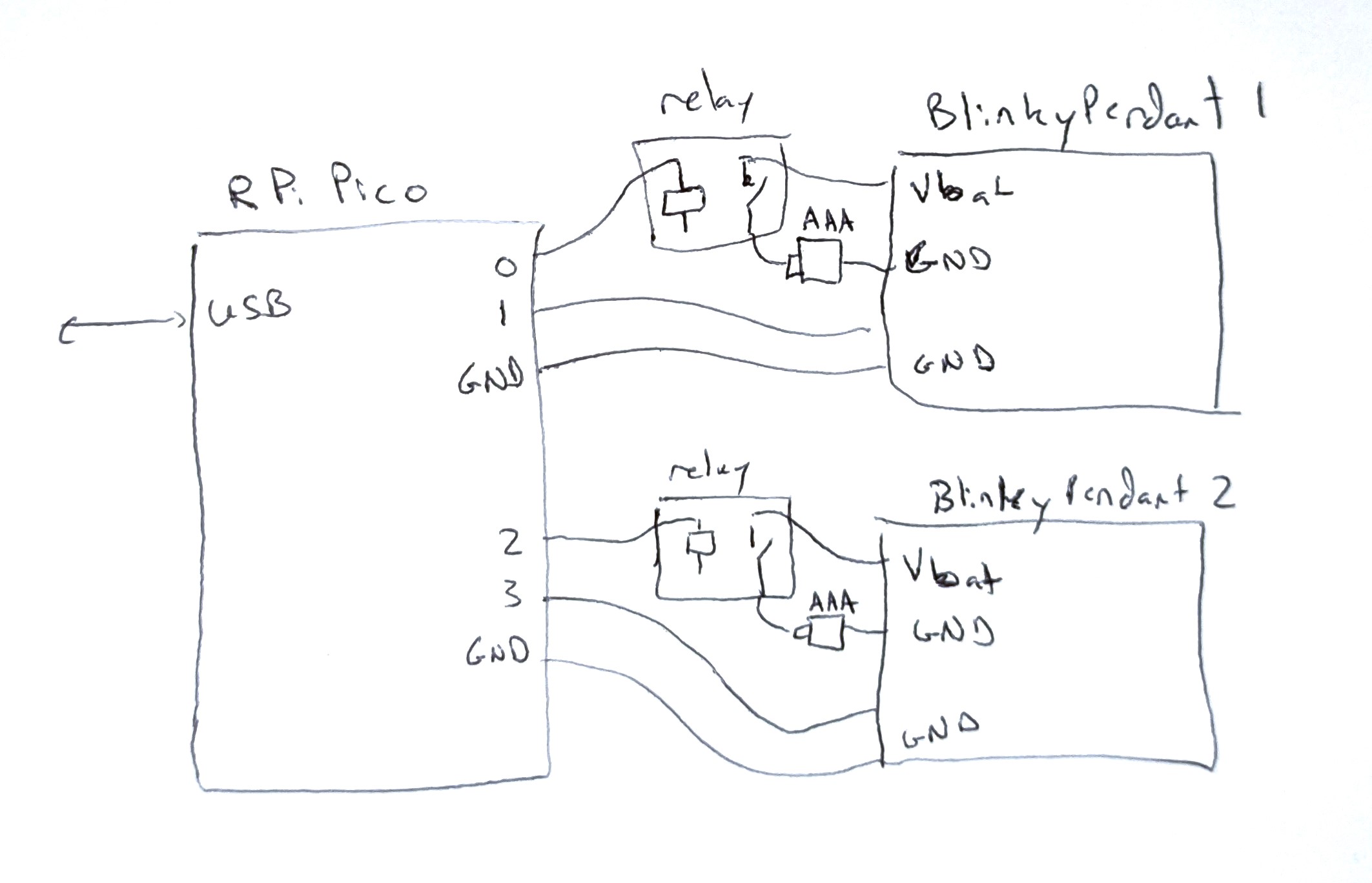
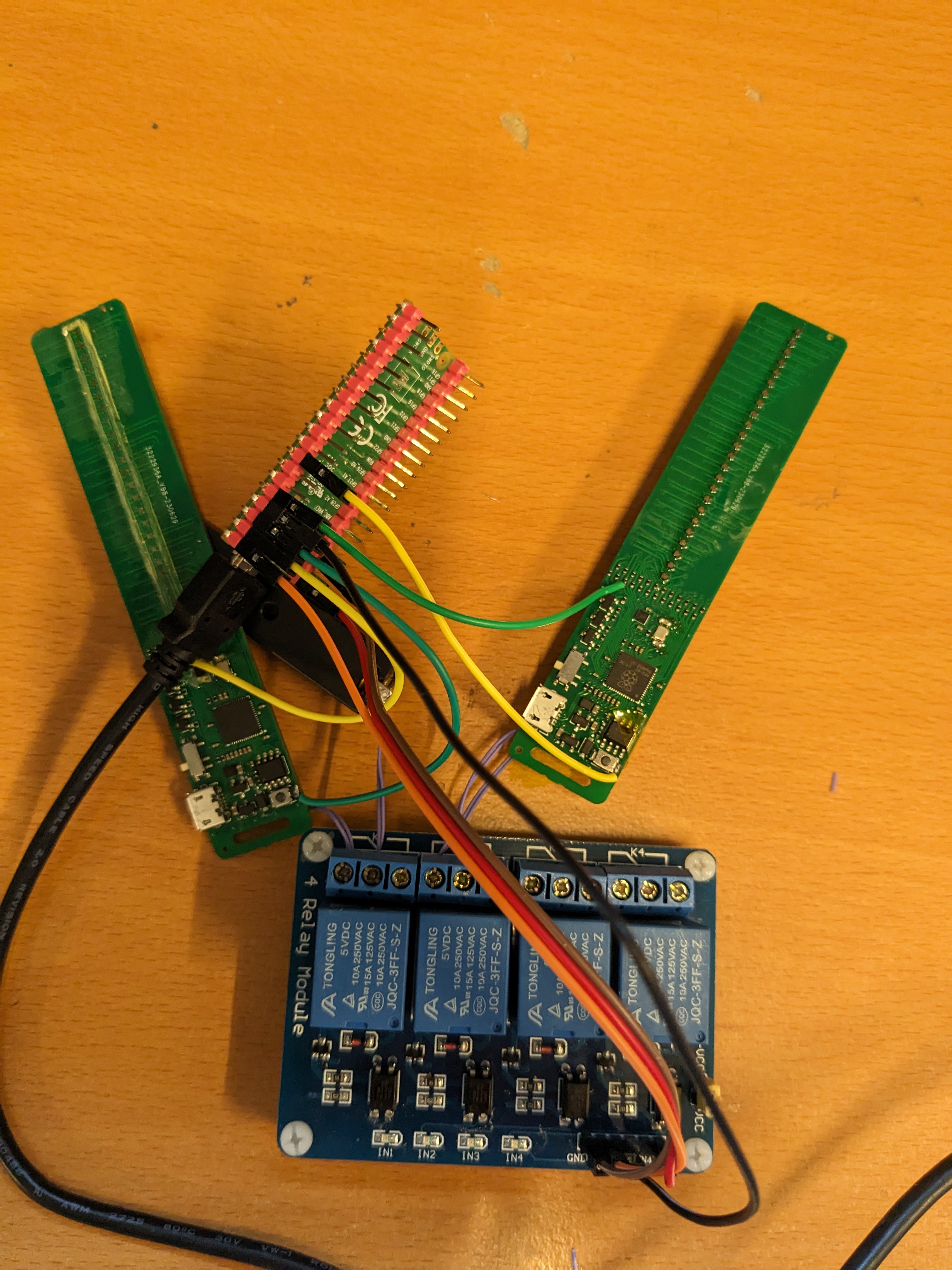
An RPi Pico with the ice40 flasher circuit was configured to control the power to two BlinkyPendants. A feedback GPIO output on each of the BlinkyPendants was configured to be set to ‘high’ after booting. The Pico was used to enable power to a board, sample the gpio output to see if the board booted, disable power to the board, and then repeat. The process was controlled by a script running on a PC:
from usb_test import IceFlasher
import time

d = IceFlasher()

d.gpio_set_direction(0,True)
d.gpio_set_direction(1,False)
d.gpio_set_direction(2,True)
d.gpio_set_direction(3,False)

p1 = 0
f1 = 0
p2 = 0
f2 = 0

while True:
    d.gpio_put(0,True) # On
    d.gpio_put(2,True) # On
    time.sleep(1)

    if d.gpio_get(1):
        p1 += 1
    else:
        f1 += 1
    if d.gpio_get(3):
        p2 += 1
    else:
        f2 += 1
    print(f'pass:{p1} fail:{f1}  pass:{p2} fail:{f2}')

    d.gpio_put(0,False) # Off
    d.gpio_put(2,False) # Off
    time.sleep(.1)
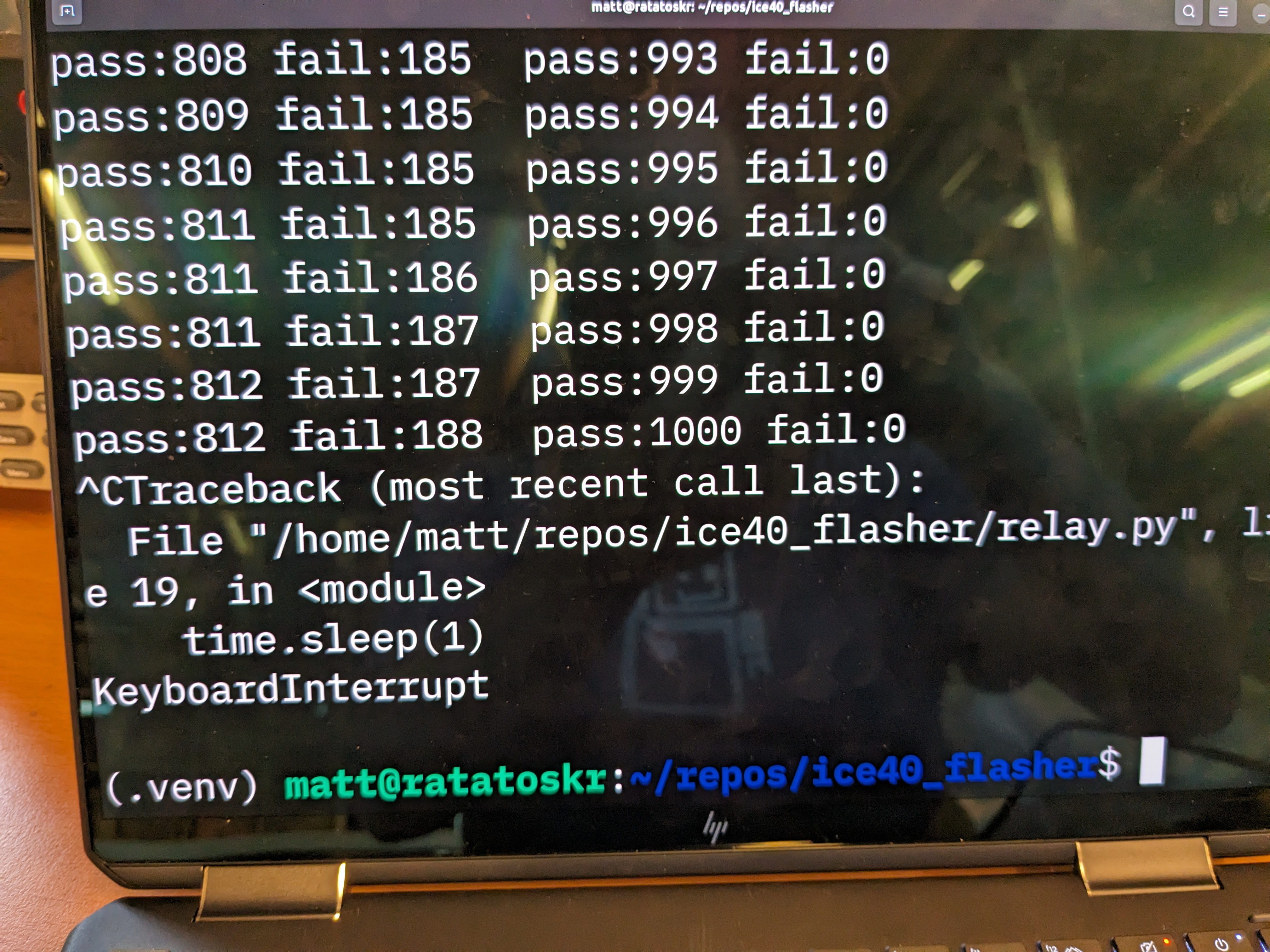
The results of this test were very conclusive: with either or both of the above fixes applied, the test board manged to boot 100% of the time. The reference board, with neither fix applied, only managed to boot 80% of the time, demonstrating that the test platform was capable of triggering the boot issue.
Conclusion
Special care needs to be taken when using an RP2040 in a custom ciruit. The SDK defaults are more sensitive to small crystal instabilities than other microcontrollers that the author has experience with. One could make the argument that the BlinkyPendant hardware design was marginal, and that it’s better for the software to refuse to work so that the hardware issue can be surfaced during prototyping. Unfortunately, measuring crystal start-up time is tricky and requires some specialist equipment (active oscilloscope probes). Conceptually, it might be better for the SDK to default to a less restrictive setting by default, so that the board has the best chance of working, especially over process and temperature environments that it is likely to face in the field.